Ball Component
The ball component is a sphere cut at two parallel planes with a threaded cylindrical hole centered around the sphere centerline and perpendicular to the two cut-off planes. Given that the average distance between the top of the ear to the outer corner of the eye is 70 mm, the ball diameter will not exceed 70 mm. Also, the specification requires a 70° insonation angle. In order to satisfy this specification, the following calculation was used to generate the minimum radius of the cut-off plane.
Headset Dimension Calculations
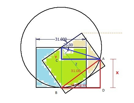
We have two probe locations: one is the indicated by the blue area (Location 1), and the other by the yellow area (Location 2). Overlaps are indicated by light green. The dark green lines are the center of the probe, and the angle below the two lines is 35°. Knowing the bottom left corner of the probe at Location 2 will not be higher than the bottom right corner of the probe at Location 1, we see that Line AC represents half the bottom chord for the ball component. The distance between B and C is calculated using the red triangle: x = 31sin(35°) = 17.8 mm. To have a valid ball component, the radius of the ball needs to exceed 17.8 mm. Thus we have two constraints on the ball’s radius:
Since the socket thickness would take up a 5 mm radius, and a 5 mm radius is needed to provide additional workspace for the strap and collodion attachments on the pedestal, we conveniently pick the radius to be 25 mm.
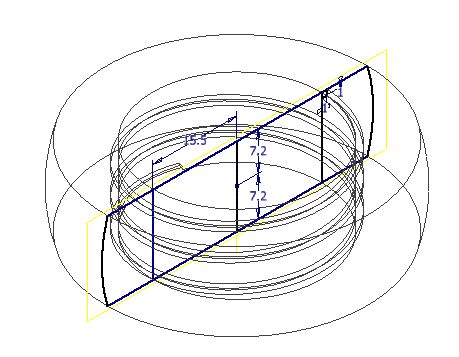
Given r = 25 mm and x = 17.8 mm from previous calculations, the distance between the ball origin to the bottom chord surface would be:
Given r = 25 mm and x = 17.8 mm from previous calculations, the distance between the ball origin to the bottom chord surface would be:
Using the trigonometry marked as the blue triangle in the figure,
Thus, the half of the two parallel chords would be 23.94 mm.
Additionally, the surface of the hole needs to have threads matching the pattern on the probe so the probe can be inserted in the hole. The actual threads applied are 1 mm x 1 mm cross section thread indent that runs clockwise from top to bottom with 2.8 revolutions.
Additionally, the surface of the hole needs to have threads matching the pattern on the probe so the probe can be inserted in the hole. The actual threads applied are 1 mm x 1 mm cross section thread indent that runs clockwise from top to bottom with 2.8 revolutions.
3D View of the Ball Component
